GENERAL BUILDING DATA
|
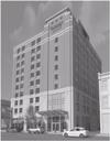
Fairfield Inn & Suites |
LOCATION: |
Pittsburgh, PA |
BUILDING OCCUPANT: |
Federal Street Hospitality Associates |
OCCUPANCY: |
Hotel |
SIZE: |
80,000 SF |
NUMBER STORIES: |
10 stories + 1 story below grade |
DATES OF CONSTRUCTION: |
Not yet started |
PROJECT COST: |
Unavailable |
PROJECT DELIVERY METHOD: |
Design-Build |
PROJECT DESIGN TEAM
OWNER: |
Federal Street Hospitality Associates,LP
|
|
DEVELOPER: |
Kratsa Properties
2801 Freeport Road
Pittsburgh, PA 15238
|
|
ARCHITECT: |
Burt Hill
650 Smithfield Street
Suite 2600
Pittsburgh, PA 15222
|
|
GENERAL CONTRACTOR: |
Massaro Corporation
120 Delta Drive
Pittsburgh, Pa 15238 |
|
STRUCTURAL ENGINEER: |
Atlantic Engineering
650 Smithfield Street
Suite 1200
Pittsburgh, PA 15222 |
|
MEP ENGINEER: |
Allen & Shariff Engineering
700 River Avenue
Suite 333
Pittsburgh, PA 15212
|
|
LANDSCAPE/CIVIL ENGINEER: |
Burt Hill
650 Smithfield Street
Suite 2600
Pittsburgh, PA 15222
|
|
ARCHITECTURE
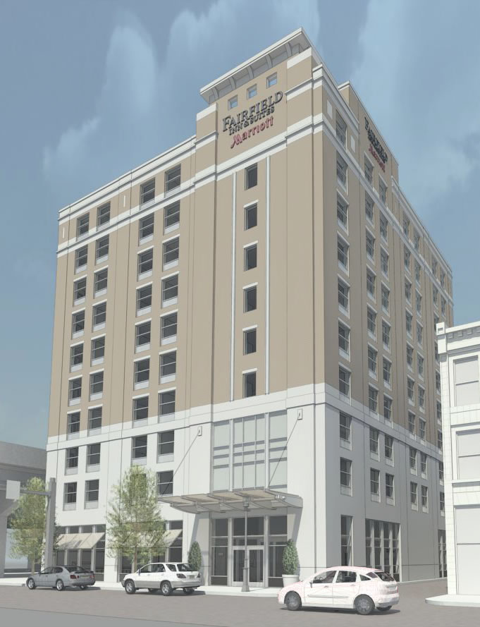
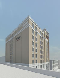
The Fairfield Inn Hotel is a 10-story building located directly across from PNC Park. The hotel is located in the heart of Pittsburgh within walking distance to downtown Pittsburgh, Heinz Field (football stadium), the new Rivers casino, and many other Pittsburgh attractions. Therefore, the hotel will accommodate tourists and visitors to the city of Pittsburgh.
This hotel occupies 135 guest rooms with an indoor pool and fitness center. The basement holds the electrical, mechanical, and maintenance rooms, along with the laundry room and break room for employees. Guests will enter an 18’ lobby off the Federal St. entrance into an open-plan space including a large reception desk, breakfast area, and seating area featuring a cherry finished wood fireplace.
CODES & ZONING
Fairfield Inn & Suites is located in the DR-B, Downtown Riverfront District B, zoning district which is a mixed-use zoning district according to the City of Pittsburgh Zoning Commission.
IBC 2006
ASTM
ACI 318
IFC 2006
IEC 2006
IMC 2006
NFPA 13
No historical requirements apply to this site.
BUILDING FACADE
The building envelope for the Fairfield Inn is similar for all walls (North, South, East, & West). Each wall is a precast plank and load bearing masonry wall structure. The lateral system is reinforced masonry shear walls. Cast stone decorates the exterior of the building from the first level to the top of the third level. A cavity wall with brick veneer begins on the fourth level and extends to the roof of the building. On the north elevation, there are two 56’ x 18’ bond faced brick detailed rectangles accenting this view of the building from the highway.
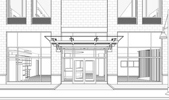
The entrance to the hotel is shaded by a 19’ x 10’ steel supported, tempered glass. Smaller tempered glass awnings shade the remaining lobby windows. All windows and doors of lobby are part of a curtain wall system, along with the spandrel glass that extends 2 stories above the entrance. Windows throughout the rest of the building are all aluminum window systems. A metal louver and cast stone sill line the bottoms of each window. The windows are shaded from the inside of each room with ceiling mounted drapery.
The West and South elevations have attached illuminated signs identifying the building along with lighting fixtures to accent the higher penthouse area of the hotel. The north elevation faces the highway and features a large illuminated sign with lighting fixtures in the bond face brick detail on that wall.
ROOFING
The main roof is made up of a typical 8” precast concrete plank fully adhered, TPO roofing membrane, flashing membrane, and tapered insulation. The penthouse roof, or high roof, has the similar 8” precast concrete plank roofing system supported by masonry shear walls decorated with metal siding. The roof and penthouse roof are edged with metal coping.
SUSTAINABLITY FEATURES
Although this facility has a number of energy efficient features, there are no distinct substainability or LEED ratings.
ENGINEERING SYSTEMS
Structural
The structural system for Fairfield Inn & Suites consists primarily of a post-tensioned cast in place concrete system. The Fairfield Inn & suites’ foundation consists of a 12” thick concrete mat slab. The foundation is composed of primarily square 7’-6” auger cast piles and steel grade beams extending to the second floor supporting the shear walls that extend from the third floor to the roof and allowing for the 18’-0” first floor ceiling height.
The basement has a 6” concrete slab on grade with a compressive strength of (f’c) equal to 4000 psi. The 1st level consists of a 4” concrete slab on grade with compressive strength equal to 4000 psi on the south end of the building, while the rest of the floor system is a 8”untopped precast concrete plank floor. This 8” precast plank floor system is continued on all levels thru the tenth floor. The typical width of the precast plank floors are 31’-0” and 26’-0”. The floor systems support concrete masonry bearing walls. Since the floor system is a precast plank floor, there are a limited number of steel beams throughout the structure. The majority of beams that do exist in the building are the transfer beams at the 2nd level that run along the back of the elevator shafts from the west wall to the east wall, and along the back of south wall of stair B extending from the west wall to the east wall. These transfer beams range in size from W 33x118 to W 40X149. Other beams located throughout the building are W 8x18 running across the area between the back of the elevators and stair A on all levels excluding the basement.
The lateral system is reinforced concrete masonry shear wall. The exterior walls are 10” concrete masonry and the interior shear walls are 8” concrete masonry. The interior shear walls surround the staircases, and two shear walls extending from the west wall to the east wall run along the south wall of staircase B and the north wall of the elevator shafts. All shear walls should support a compressive strength (f’c) equal to 5000 psi normal weight concrete.
The roof system and smaller high roof system are the same. The roof is an 8” untopped precast concrete plank. Hoist beams support the top of the elevator shaft in the high roof system. There are a total of 6 drains located on the roof for the drainage system.
Construction
Construction for the Fairfield Inn & Suites is a Design-Build delivery method. The project is set to begin construction in October 2009. The design phase and construction phase are overlapping which makes it hard to get an exact cost for this project so soon in the construction process. The general contractor on the project is Massaro Corporation.
Electrical/Lighting
The electrical service to the building is 208/120V 3 phase 4 wire system and an emergency system. The common distribution switch board is a 208/120V 3 phase 4 wire system with a 250A bus. Each level of the hotel is supplied with 3 panel boards located in their electrical room. There are 6 additional panels for the mechanical rooms, pool, fitness center, and elevators.
There is a lighting system used throughout this building is mainly comprised of florescent and HID lighting; recessed, pendant, and industrial strip fixtures. There is also a dimming system incorporated into the lighting system for the building.
Mechanical
The Fairfield Inn & Suites’ mechanical system is designed for multiple areas of the hotel. An indoor air handling unit placed in the basement with airflow 1600 cfm services the heating and cooling of 1st floor/ lobby and corridors of the hotel. The guest rooms are equipped with mini A/C units with airflow of 530 cfm. Boilers in the basement serve the purpose of heating the remainder of the building. The roof of the hotel holds a 4200lb natural gas rooftop unit with 3400 cfm airflow servicing the building. Since the pool provides a luxury pool for its guests the building is equipped with a pool dehumidifier that removes 15 lb/hr of moisture from the air and airflow of 1620 cfm. Located in the Mechanical room is an indoor air cooling chiller and outdoor condenser to service the building.
Fire Protection
Fairfield Inn & Suites will be equipped with an automatic sprinkler system installed on all levels in accordance with NFPA 13 for building above 4 stories. Smoke alarms will be installed in all sleeping/guest rooms and corridors. Visual alarms will also be placed in all guest rooms. All staircases and elevator shafts are 2 hour rated. There is an automatic fire pump with 750 gpm flow, 100 psi feet head, 75 HP, and 3560 rpm with a 208V 3 phase system. Along with the fire pump, a jockey pump with 10 gpm, 110 psi feet head, 3 HP, and 3560 rpm with the same 208V 3 phase system, is placed basement of the hotel.
Transportation
The new Fairfield Inn & Suites will incorporate two stair towers and two elevator shafts. The two elevators will be in the central core of the hotel off the lobby. The elevator will extend from the basement to all levels, with the elevator shaft over run continuing to the roof level. One stair (Stair B) will be directly across from the elevators, off the elevator lobby in the central core of the building. Stair B extends from the basement to the roof of the hotel. The other stair (Stair A) is located along the north wall and north elevation of the hotel. Stair A extends from the basement to all levels except the roof. This stair stops on the tenth floor.
Telecommunication
The central controls for the Fairfield Inn & Suites’ telecom system will be kept in the basement. The telecom system for the Fairfield Inn & Suites includes telephones, speaker/microphone system, and computers connected to a central network.
|